Table of Contents
Introduction to Pneumatic Valves in Robotics
Pneumatic valves are the control center of every compressed air system, directing airflow to cylinders, grippers and other actuators. In robotics and automation, pneumatic valves enable rapid and reliable control over movement, allowing engineers to start, stop, reverse and modulate motion with ease. Whether powering a pick‑and‑place robot, a collaborative arm or a packaging machine, pneumatic valves determine the direction, timing and speed of compressed air delivered to actuators.
Because pneumatics use clean, dry air, pneumatic valves are inherently safe and suitable for environments where leaks of hydraulic oil or electrical sparks would be hazardous. Throughout this comprehensive guide, the term pneumatic valves appears in every paragraph to ensure clarity for readers and to reinforce the focus keyword for search optimization.
Robots rely on pneumatic valves to translate electrical or mechanical signals into pneumatic motion. Solenoid coils, air pilots or manual levers shift the internal components of pneumatic valves, allowing pressurized air to flow or to vent. The quick response and high cycle rates of pneumatic valves make them ideal for high‑speed automation. For robots, pneumatic valves offer a balance between the simplicity of mechanical systems and the flexibility of programmable control. By understanding how pneumatic valves work and how to select them, designers can create responsive and dependable robotic systems.
How Pneumatic Valves Work in Automation
Pneumatic valves control the direction, rate and timing of air flow by opening, closing or diverting ports within the valve body. Compressed air enters a supply port, and depending on the valve’s position, it flows to one of several output ports while exhaust ports vent air to atmosphere. The valve’s internal mechanism, either a spool or a poppet, determines which paths are open.
For example, a 5/2 pneumatic valve has five ports (one supply, two outputs, two exhausts) and two positions; in one position, air flows to output A while output B vents, and in the other position, air flows to output B while output A vents. Pneumatic valves can be actuated by solenoids (electromagnets), mechanical cams, manual levers or pilot air signals. When a robot’s controller energizes a solenoid coil, the pneumatic valve shifts, redirecting air and causing a cylinder to extend or retract. The rapid switching ability of pneumatic valves enables precise timing and high speeds.
In robotics, pneumatic valves often interface with programmable logic controllers (PLCs) or microcontrollers. A PLC sends a digital signal to the solenoid coil, which moves the spool or poppet to change the valve’s state. The controller monitors sensors on cylinders to ensure that motions complete before the next step.
Because pneumatic valves operate quickly, they can accomplish hundreds of cycles per minute, allowing robots to meet demanding throughput targets. At the same time, the simple construction of pneumatic valves, few moving parts and robust sealing, contributes to long service life with minimal maintenance. Understanding how pneumatic valves direct flow and respond to control signals is fundamental to designing reliable automation.
Types of Pneumatic Valves for Robotics and Automation
Pneumatic valves come in various configurations based on port count, positions, internal mechanism and actuation method. In robotics, certain types of pneumatic valves excel because they provide the necessary control while fitting within the constraints of robotics equipment. This section introduces the major categories of pneumatic valves used in robotics and automation.
3/2 Directional Pneumatic Valves
Three‑port two‑position (3/2) pneumatic valves have one supply port, one outlet port and one exhaust port. They switch between supply to the outlet (pressurizing the actuator) and exhaust (venting the actuator). In robotics, 3/2 pneumatic valves often control single‑acting cylinders and grippers. For example, a 3/2 valve can supply compressed air to a single‑acting clamp to close it and then release air to let the spring or gravity open the clamp. These pneumatic valves are simple and cost‑effective, offering quick switching for on/off control of small actuators. When selecting 3/2 pneumatic valves, consider the port size and flow rate to ensure that the cylinder’s speed meets the robot’s cycle time requirements.
4/2 and 5/2 Directional Pneumatic Valves
Four‑port two‑position (4/2) pneumatic valves and five‑port two‑position (5/2) pneumatic valves are the workhorses of robotics. They control double‑acting cylinders, directing air to extend or retract the piston. A 4/2 valve has one supply port, two output ports and one shared exhaust port. This configuration is common for double‑acting cylinders where independent exhaust control is not necessary.
A 5/2 valve, however, provides separate exhaust ports for each output, allowing precise control of exhaust backpressure and venting. In robotics, the choice between a 4/2 and 5/2 pneumatic valve depends on whether independent exhaust control is beneficial. Independent exhaust can reduce cross‑contamination between the extend and retract circuits, improve speed control and allow additional silencers on each exhaust port. Many 5/2 pneumatic valves also offer manual overrides to shift the valve without electrical power, useful during maintenance.
These pneumatic valves can be actuated by single solenoids with springs or by twin solenoids (bi‑stable). In mono‑stable 4/2 and 5/2 pneumatic valves, a solenoid energizes the valve to one position, and a spring returns it to the default position when power is removed. In bi‑stable valves, two solenoids control each position, and the valve remains in the last energized position until the opposite coil is energized.
In robotics, mono‑stable pneumatic valves provide a fail‑safe default state, while bi‑stable valves reduce power consumption because current flows only when changing positions. Engineers must consider the control architecture and safety requirements when choosing between mono‑stable and bi‑stable pneumatic valves.
5/3 Directional Pneumatic Valves
For applications requiring a mid‑position, three‑position five‑port (5/3) pneumatic valves provide additional functionality. These valves have three positions: extend, retract and a center position. The center position can be center‑closed (all ports blocked), center‑exhaust (all ports open to exhaust) or center‑pressure (outputs connected to supply). In robotics, 5/3 pneumatic valves allow cylinders to stop mid‑stroke, hold a position or depressurize both sides.
For example, in a robot carrying a fragile object, a center‑closed 5/3 valve can hold the cylinder at a set position, preventing drift. In a safety situation, a center‑exhaust 5/3 valve can vent all air to make the cylinder limp and safe for workers to handle. Although 5/3 pneumatic valves are less common than 4/2 or 5/2 valves, they are invaluable when mid‑stroke control or safety features are required. Selecting the correct center function depends on whether the robot must hold, release or depressurize during the center state.
Spool vs Poppet Pneumatic Valves
A major distinction among pneumatic valves lies in their internal mechanism: spool or poppet. Spool pneumatic valves use a cylindrical spool with grooves and lands that open and close flow paths as the spool shifts. Poppet pneumatic valves use a sealing element (disk or cone) that lifts off a seat to open and is pressed back by a spring to close. Each design offers unique advantages and disadvantages.
According to Tameson, poppet pneumatic valves have lower cost, are less susceptible to contamination, require lower maintenance, and provide a fast response time. Because the poppet seals the exhaust before allowing flow, poppet valves have a closed crossover, preventing intermediate states and ensuring precise switching. They also offer higher flow rates due to a larger internal surface area and lower friction, resulting in longer life. However, poppet pneumatic valves require higher actuation force, are not balanced, and are not recommended for vacuum or back‑pressure applications.
Spool pneumatic valves, on the other hand, require less force to actuate and are balanced, meaning that pressure at any port does not influence the spool’s motion. Spool pneumatic valves provide constant response time and can be used to lock pressure downstream. They are versatile because they handle multiple flow paths and can be normally‑open, normally‑closed, selector or diverter valves.
However, spool pneumatic valves have lower flow rates due to smaller internal surface area, an open crossover during switching (all ports momentarily connected), and seals that wear over time, making them more susceptible to contamination and requiring more maintenance. When deciding between spool and poppet designs, engineers must consider the required flow rate, contamination tolerance, actuation force and whether balanced pressure and complex flow paths are necessary. In robotics, spool pneumatic valves are often used for precise, balanced control and for vacuum or downstream pressure applications, while poppet pneumatic valves are chosen for fast response and high flow.
Solenoid‑Actuated Pneumatic Valves
Solenoid pneumatic valves are actuated electrically by energizing a coil that moves the spool or poppet. These pneumatic valves are ubiquitous in robotics because they interface directly with PLCs, microcontrollers and distributed I/O systems. Solenoid pneumatic valves can be direct acting or pilot operated. Direct acting pneumatic valves have the coil move the sealing element directly; they switch quickly and have no minimum pressure requirement, making them ideal for low‑pressure or vacuum applications.
Pressure assisted pneumatic valves use pilot pressure to shift the spool; they handle higher flow rates and pressure with smaller solenoids but require a minimum supply pressure to operate. Engineers must choose solenoid pneumatic valves with appropriate coil voltage (24 V DC or 110 V AC), duty cycle and connector style. For robotics, 24 V DC coils are common to integrate with industrial control systems. When specifying solenoid pneumatic valves, ensure the coil’s power consumption and duty cycle align with the robot’s power supply and control strategy.
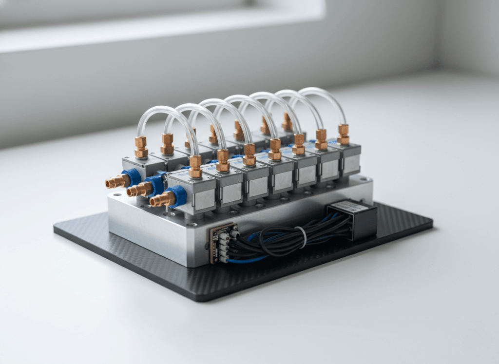
Manifold Valve Banks and Valve Islands
To simplify wiring and plumbing, multiple pneumatic valves can be mounted on a manifold or valve island. A manifold groups several pneumatic valves together, sharing a common supply and exhaust manifold while providing individual outputs. Valve islands add a digital communication module (EtherNet/IP, Profinet, CANopen, IO‑Link) that allows the robot controller to address each valve individually over a fieldbus.
This reduces wiring complexity and enables advanced diagnostics and status monitoring. In robotics cells with many actuators, valve manifolds reduce tubing length and reduce response time. When designing a valve manifold for pneumatic valves, pay attention to the flow capacity of each valve, the total air consumption, and the compatibility with the robot’s communication protocol. Standardizing on a single manufacturer’s valve island system can simplify maintenance and spare parts inventory.
Key Performance Specifications of Pneumatic Valves
Designing with pneumatic valves requires understanding several performance parameters that influence the behavior of robotic systems. These specifications help engineers match pneumatic valves to the requirements of speed, precision, load and environment.
Flow Coefficient (Cv) and Air Consumption
The flow coefficient, often expressed as Cv or Kv, quantifies the volume of air that can pass through a valve at a given pressure drop. Higher Cv values indicate that pneumatic valves can pass more air, enabling faster cylinder movement. Undersized valves restrict flow, reducing speed and causing inconsistent motion.
When specifying pneumatic valves for robotics, calculate the cylinder volume and cycle time to estimate the required flow rate. Select pneumatic valves with sufficient Cv to deliver that flow at the available pressure, accounting for pressure drop across fittings and tubing. Remember that spool pneumatic valves typically have lower flow coefficients than poppet pneumatic valves due to their internal geometry. If high speed is critical, choose poppet pneumatic valves or spool valves with larger port sizes.
Response Time and High‑Speed Robotics
Response time measures how quickly pneumatic valves shift from one state to another after receiving a control signal. In high‑speed robotics, response time directly affects cycle time and precision. Poppet pneumatic valves often provide faster response than spool valves because the poppet travels a shorter distance to open or close the flow path.
Direct acting solenoid pneumatic valves also respond rapidly because the coil directly moves the sealing element without pilot pressure. For applications requiring cycle times of a few milliseconds, such as sorting small components, choose pneumatic valves with low response times and minimal hysteresis. To achieve the best performance, mount pneumatic valves close to actuators to reduce tubing length and air transit time.
Pressure Rating and Seal Material Compatibility
Pneumatic valves operate at specific pressure ranges. Most industrial valves are rated for supply pressures up to 8 bar (120 psi). Exceeding the rated pressure can cause leaks or mechanical failure. Some pneumatic valves are pressure‑assisted and require a minimum pressure to operate, while direct acting valves can function with zero pressure differential. Seal materials, such as nitrile, Viton, EPDM, determine the valve’s chemical and temperature compatibility.
For robots in food or pharmaceutical environments, choose pneumatic valves with FDA‑approved seals and stainless steel bodies. In high temperature environments, select seals that withstand the heat. The internal sealing design also influences leak rate and life; poppet pneumatic valves typically offer tighter seals with minimal leakage. Always match the valve’s pressure rating and seal material to the application.
Duty Cycle and Coil Heat in Solenoid Valves
The duty cycle of a solenoid valve refers to the percentage of time the coil can be energized without overheating. Continuous duty (100%) valves can remain powered indefinitely, while intermittent duty valves require off time to cool. In robotics, valves often cycle frequently, so continuous duty is preferred to avoid coil burn‑out.
Coil heat dissipates into the valve body and surrounding air; in high‑density valve manifolds, ensure adequate ventilation. Some solenoid valves include built‑in thermal protection to prevent coil damage. When specifying solenoid pneumatic valves, verify coil wattage, duty cycle and ambient temperature limits. Overheating can cause coil insulation to degrade, leading to short circuits or failure.
Noise Control and Exhaust Management
Exhausting air from pneumatic valves can create noise and blow contaminants into the workspace. Silencers or mufflers fit onto exhaust ports to reduce noise and capture oil mist.
In robotics, noise reduction improves worker safety and reduces fatigue. For 5/2 pneumatic valves, separate exhaust ports allow independent mufflers, while 4/2 pneumatic valves have a single exhaust; choose the configuration that meets noise and cleanliness requirements. In cleanroom or sensitive environments, fully ported valves allow all exhaust air to be captured and vented away from the work area. Always consider the exhaust path when selecting pneumatic valves.
Selecting Pneumatic Valves for Robotics and Automation Applications
Choosing the right pneumatic valves for a robotic application requires analyzing the task requirements, environment and integration constraints. Here are guidelines for selecting pneumatic valves that align with robotics needs.
High‑Speed Pick‑and‑Place Robots
Pick‑and‑place robots require rapid cylinder extension and retraction to maintain throughput. For these robots, choose pneumatic valves with high flow coefficients and fast response times. Poppet pneumatic valves provide the highest flow and quick switching, making them ideal for high‑speed pick‑and‑place tasks. Select 5/2 or 4/2 pneumatic valves with adequate Cv, and mount them close to cylinders to minimize delay.
Ensure that the solenoid coils have a 100% duty cycle to handle frequent switching. Because these robots may run thousands of cycles per hour, valve longevity and maintenance should be considered; opt for low maintenance poppet pneumatic valves or balanced spool valves with durable seals.
Precision Assembly and Closed‑Loop Control
In precision assembly or inspection tasks, robots must move parts gently and stop accurately. Use spool pneumatic valves for precise flow control and balanced operation; spool valves maintain downstream pressure and handle complex flow paths needed for specialized fixtures.
For multi‑position control, choose 5/3 center‑closed or center‑pressure valves to hold cylinders mid‑stroke. Integrate flow control valves to fine‑tune speed, and use sensors on cylinders for feedback to a PLC. If contamination is a concern, such as in electronics assembly, select spool pneumatic valves with filters and ensure air supply cleanliness. The slightly slower response of spool valves is acceptable when precision and stability take precedence over speed.
High‑Load Fixturing and Safety
Robotic fixturing often involves clamping heavy workpieces or locking joints during machining. These applications need pneumatic valves that maintain pressure without leakage and that can be piloted externally for safe release. Choose spool pneumatic valves that can lock downstream pressure and support vacuum or back‑pressure conditions.
For safety, incorporate manual override or air pilot valves that vent the system when power is removed. Pressure regulators upstream of the pneumatic valves ensure that clamping force is consistent, while pressure switches monitor the clamp state. In machine‑tending robots, use 3/2 spring return pneumatic valves on clamps so that clamps release if air pressure fails, protecting workers during maintenance.
Collaborative Robots and Human–Machine Interaction
Collaborative robots (cobots) work alongside humans, requiring safety and compliance. Pneumatic valves used in cobots must enable soft and controlled motion. Use poppet pneumatic valves for quick response and adjustable flow control valves for smooth acceleration and deceleration.
If the robot uses vacuum grippers, include vacuum generators and ejector valves integrated into the valve manifold. Choose 5/3 center‑exhaust valves to vent cylinders quickly if an emergency stop is triggered. For cobots, integrate sensors and safety-rated valves that can meet performance level (PL) or category requirements of ISO 13849. Pneumatic valves for cobots must be reliable, low noise and easily integrated into safety circuits.
Environmental and Hygiene Considerations
Robots may operate in environments with dust, moisture, chemicals or high hygiene requirements. For dusty environments, select poppet pneumatic valves or spool valves with large clearances and less susceptibility to contamination.
Use filters and air dryers to maintain air quality. In washdown areas or food processing, choose pneumatic valves made from stainless steel with FDA‑approved seals and fully ported designs that allow exhaust to be captured. For cleanrooms, use valves that minimize particle generation and use non‑lubricated or dry-lubed seals. Environmental compatibility ensures the longevity of pneumatic valves and protects product quality.
Integration Considerations: PLCs, Manifolds and Fittings
Integrating pneumatic valves into a robotic system goes beyond selecting the valve itself. Consider how pneumatic valves connect to controllers, manifolds, tubing and sensors.
PLC, Fieldbus and IO‑Link Integration
Modern robots use PLCs or IPCs with digital outputs to control solenoid pneumatic valves. When using discrete outputs, each valve’s coil connects to a dedicated output point. To reduce wiring, valve islands with fieldbus modules (EtherNet/IP, Profinet, CANopen) allow dozens of pneumatic valves to communicate via a single network cable.
Each valve island includes a power supply and communication node; the PLC sends commands and receives diagnostic feedback. Newer protocols like IO‑Link allow sensors and pneumatic valves to communicate diagnostic data directly to controllers, enabling predictive maintenance. When designing the control architecture, choose a communication protocol that aligns with the rest of the robot’s automation equipment.
Manifold Layout and Mounting
Valve manifolds reduce clutter and shorten air lines. When arranging pneumatic valves on a manifold, group valves controlling similar actuators together to minimize cross talk and pressure drop. Provide separate supply and exhaust manifolds to isolate circuits. In robotics, mount manifolds close to the robot to reduce tubing length, but outside of moving cable tracks to minimize weight on the arm. Provide ample space for wiring and maintenance access. Use mounting brackets that dampen vibration and provide strain relief for tubing. Label each valve and port to simplify troubleshooting. By thoughtfully arranging pneumatic valves on manifolds, engineers improve reliability and ease of maintenance.
Tubing and Fitting Routing
Proper tubing and fitting selection ensures that pneumatic valves deliver air efficiently and without leaks. Use push‑to‑connect fittings for quick assembly and maintenance, and compression fittings for high‑pressure applications or where vibration is present. Match tubing material to the environment: polyurethane for flexibility, nylon for chemical resistance, PTFE for high temperatures. Avoid sharp bends or long runs that increase pressure drop. Secure tubing to prevent vibration and abrasion.
In robotics, route tubing along the robot’s cable dress pack and avoid interfering with moving parts. Use quick‑disconnect fittings or manifolds with integrated fittings to simplify tool changes. When connecting pneumatic valves to vacuum systems, include check valves to prevent reverse flow and maintain vacuum integrity. Good tubing and fitting practice ensures that pneumatic valves operate at their full potential.
Leak Testing and Maintenance Routines
Leaks waste compressed air and cause inconsistent performance in pneumatic valves. Implement leak detection during installation and maintenance. Use soapy water, ultrasonic leak detectors or smart flow sensors to identify leaks. For manifolds, check gaskets and O‑rings; for fittings, ensure proper insertion and tightening. Replace worn seals and lubricate moving parts as recommended by manufacturers.
Schedule periodic inspections of pneumatic valves, including actuation tests, coil resistance measurements, and cleaning of exhaust mufflers. For pressure assisted pneumatic valves, verify that pilot pressure lines are clear and that pilot orifices are not blocked. In robotics, preventive maintenance minimizes downtime and ensures safe operation. By integrating leak testing into maintenance routines, engineers protect pneumatic valves and associated systems.
Common Failure Modes of Pneumatic Valves and How to Prevent Them
Pneumatic valves are durable, but failures can occur if components are misapplied or neglected. Understanding common failure modes helps engineers design robust systems and implement preventive measures.
Spool Sticking and Contamination
Spool pneumatic valves are susceptible to contamination because of their tight clearances and multiple seals. Dirt, debris or oil can cause the spool to stick, leading to delayed or incomplete switching. This results in cylinders that fail to move or that jerk during motion. To prevent sticking, supply clean, dry air by installing filters and air dryers. Use maintenance practices such as regular flushing and cleaning of valves. Select spool pneumatic valves with dust‑resistant seals or consider poppet valves in dirty environments. In robotics, incorporate sensors to detect valve malfunctions and provide early warnings.
Coil Overheating and Electrical Failure
Solenoid coils generate heat when energized. If the duty cycle exceeds the coil’s rating or if ambient temperature is high, the coil can overheat, causing insulation failure or short circuits. Overheating may also occur if the valve is clogged and the coil remains energized while trying to shift.
To prevent coil failure, specify pneumatic valves with continuous duty coils for high cycle applications, ensure adequate cooling, and monitor coil current. Consider using bi‑stable pneumatic valves to reduce on‑time or adding heat sinks. For robotics, place valves in ventilated enclosures and monitor coil temperature with sensors. Replace coils that show signs of discoloration or smell burnt.
Valve Chatter and Undersized Flow Capacity
Valve chatter refers to rapid oscillation of the valve between states, producing noise and inconsistent flow. It often occurs when pneumatic valves are undersized for the air flow demand or when the pilot pressure is unstable. Chatter can reduce cylinder speed and cause wear. Prevent chatter by sizing valves correctly based on calculated flow requirements and selecting valves with stable actuation.
Use accumulators or regulators to dampen pressure fluctuations. In robots with high flow demands, choose poppet pneumatic valves or spool valves with larger ports. Ensure supply lines provide steady pressure and that pilot lines are not restricted. Addressing sizing and pressure stability issues prevents valve chatter.
Seal Wear and Leakage
Seals in pneumatic valves wear over time due to friction, pressure cycling and contamination. Worn seals cause internal leakage, resulting in slower cylinder movement and wasted air. Regular maintenance and seal replacement are essential. Use high‑quality seals rated for the application’s temperature and chemical exposure. In spool pneumatic valves, ensure that O‑rings are lubricated and replaced when they show signs of flattening or cracking. In poppet pneumatic valves, check the sealing surface for wear and replace the poppet if necessary. By monitoring air consumption and cycle times, engineers can detect seal wear early and prevent unexpected failures.
Pilot Pressure Problems
Pressure assisted pneumatic valves rely on pilot pressure to shift the main valve. If pilot pressure is too low due to leaks or restrictions, the valve may not operate correctly. Ensure that pilot lines are sized properly and free of obstructions. Use filters in pilot lines to prevent contamination. In robots with fluctuating main supply pressure, consider adding a dedicated pilot pressure regulator. In vacuum systems, choose direct acting pneumatic valves instead of pilot operated valves to avoid pilot pressure problems. Paying attention to pilot circuit design ensures reliable operation of pneumatic valves.
Case Studies: Pneumatic Valves in Robotics and Automation
Case Study 1: High‑Speed Sorting Robot with Poppet Valves
A manufacturing plant uses a robot to sort small components into bins at 120 cycles per minute. Each cycle requires the robot to extend a cylinder, pick up a part, retract, move and deposit the part. To meet the speed requirement, engineers choose 5/2 poppet pneumatic valves with high flow coefficients and fast response times. The valves supply air to double‑acting cylinders with short tubing runs.
Because the poppet valves provide closed crossover, the cylinders switch cleanly without intermediate states, avoiding jerky motion. The robot achieves consistent high speed without compromising precision. Silencers on the exhaust ports reduce noise, and sensors on the cylinders feed back position to the PLC. Regular maintenance checks ensure the poppets remain clean and operate reliably.
Case Study 2: Precision Robot with Spool Valves and Mid‑Position Hold
A robotic assembly cell requires placing delicate electronic components onto circuit boards with sub‑millimeter accuracy. Engineers choose 5/3 center‑closed spool pneumatic valves to control the axes because these pneumatic valves can hold cylinders mid‑stroke without drifting. The spool design locks downstream pressure and balances incoming pressure, ensuring smooth, steady movement. Flow control valves fine‑tune the extension and retraction speed.
The valve bank communicates with the PLC over EtherNet/IP, sending diagnostic data such as actuation counts and error codes. When the robot experiences misalignment, the pneumatic valves send an alarm. Preventive maintenance ensures the spool seals remain lubricated and free of debris. The combination of spool pneumatic valves, flow controls and feedback provides the precision needed for delicate assembly.
Case Study 3: Safety‑Focused Clamping System
In a machining center, robots hold heavy workpieces in place during milling and drilling. Safety requires that clamps maintain force even if electrical power is lost. Engineers use spring return 4/2 spool pneumatic valves in combination with pressure switches. When the solenoid is energized, the spool shifts, clamping the workpiece. If power fails, the spring returns the spool to the default position, which vents the clamp and releases the workpiece automatically. Pressure switches monitor the clamp pressure and send signals to the robot’s controller. Because spool valves can maintain downstream pressure and handle back pressure, they are ideal for this application. The safety system protects operators during tool change or power outages.
Case Study 4: Vacuum Gripper System with Valve Island
A packaging robot uses a vacuum gripper to pick up and place bags. The system uses a valve island integrating multiple 3/2 pneumatic valves for the vacuum generators and blow‑off valves. The island communicates via IO‑Link, providing diagnostic data to the PLC. The 3/2 pneumatic valves control vacuum on/off and blow‑off to release the bags. Because vacuum systems can be sensitive to contamination, engineers choose poppet pneumatic valves with low maintenance and fast response. Fully ported valves allow all exhaust air to be captured and vented away. Flow control valves adjust vacuum speed, and check valves prevent vacuum loss. The result is a reliable vacuum gripper system with integrated diagnostics for predictive maintenance.
Case Study 5: Collaborative Robot with Soft Pneumatic Motion
A collaborative robot picks parts from a tray and places them into a machine. The robot must move smoothly and comply with safety standards for working near humans. Engineers select spool pneumatic valves with adjustable flow controls to provide gentle, controlled motion.
They use 5/3 center‑exhaust pneumatic valves so that, in an emergency stop, all cylinders vent and become compliant. The valves are mounted on a modular manifold with fieldbus communication. A sensor network monitors cylinder positions and valve health. Because spool pneumatic valves handle back pressure, the system can hold a position temporarily if needed. The combination of controlled speed and fail‑safe venting enables safe human–robot collaboration.
Conclusion — Mastering Pneumatic Valves for Precision Robotics
Pneumatic valves are essential components of robotic and automation systems, controlling the direction and flow of compressed air to actuators. By understanding how pneumatic valves work, the differences between 3/2, 4/2, 5/2 and 5/3 configurations, and the pros and cons of spool versus poppet designs, engineers can select the right valve for each robotic task.
Key performance parameters, flow coefficient, response time, pressure rating, duty cycle and exhaust management, guide valve selection for high‑speed pick‑and‑place operations, precision assembly, heavy‑duty clamping, collaborative robots and vacuum systems. Integration considerations, such as PLC communication, manifold layout, tubing routing and maintenance, ensure that pneumatic valves operate reliably in the context of a robot.
Preventing failure in pneumatic valves involves providing clean air, selecting appropriate seal materials, managing coil heat and sizing valves properly. Real‑world case studies illustrate how pneumatic valves enable high‑speed sorting, precise assembly, safety clamping, vacuum gripping and collaborative robot motion. With proper selection, integration and maintenance, pneumatic valves deliver speed, precision and safety for modern robotics. If you’d like guidance selecting or sourcing pneumatic valves for your robotic system, feel free to contact us, we’re here to help.